Mochi Sprout Learns Feedback: Comparing P, PI, PD, and PID
A torque pendulum, a +30° step, and one gain set — measured, not assumed
Day 1 ended with an uncontrolled pendulum: two gravity settings, one measured difference, no actuator. The obvious next question was whether a controller could hold the pendulum at a chosen angle — and what each part of a PID controller actually contributes when the answer is measured instead of asserted.
This article is Day 2. It adds a reusable scalar PID controller, a MuJoCo adapter that turns controller output into hinge torque, and a step-response comparison of baseline, P, PI, PD, and PID on the same model with the same gains. One controller settled. The rest did not, and the ways they failed are the interesting part.
There is still no walking robot, no learned policy, and no hardware. What exists is a reproducible simulation, measured numbers, and a controller you can reuse.
1. The problem Day 1 left open
Day 1's pendulum hangs at 0°, the downward equilibrium. Its motion is the free response to gravity and damping. To hold it at +30°, the motor must continuously supply the gravity holding torque. MuJoCo reports that torque for this model as +1.22625 N·m at +30°:
where kg, m/s², and m is the distance from the hinge to the centre of mass. A controller that cannot supply 1.22625 N·m at the target cannot hold it. A controller that supplies it too aggressively will overshoot and oscillate. The experiment measures where each controller lands between those two failures.
2. A controller that knows nothing about MuJoCo
The controller is deliberately simulator-independent. It lives in src/mochi_sprout/control/pid.py, imports no MuJoCo, and knows only three things: a target, a measurement, and an update interval. Its configuration is a frozen dataclass:
@dataclass(frozen=True)
class PIDConfig:
    kp: float
    ki: float = 0.0
    kd: float = 0.0
    output_min: float = -float("inf")
    output_max: float = float("inf")
The PID class exposes a small interface — reset(), update(target, measurement, dt), and a saturated flag — which any other controller can implement without touching the physical model. That separation is the point: the controller is generic code; the robot-specific part is the adapter that connects it to MuJoCo, covered in §3.
Two design choices matter for the results below.
Derivative on measurement, not on error. The derivative term is , with zero derivative on the first update. A sudden target step therefore does not produce a derivative kick — only actual motion does. The control law per update is:
Conditional anti-windup. The integral term keeps growing while the actuator cannot supply the requested output — that is integral windup. This implementation skips an integral update when the requested output already exceeds a limit and the error would drive it farther beyond that limit. Integration resumes when the error would unwind the output. The output is still clamped at the limit; anti-windup protects controller state, it does not guarantee a good response.
Gains must be finite and nonnegative, and output_min must be below output_max; the configuration validates both.
3. Connecting the controller to MuJoCo
The adapter is src/mochi_sprout/simulation/controlled_pendulum.py. It reuses the Day 1 MJCF and appends one direct-drive hinge motor: gear 1, so a ctrl value is joint torque in N·m, with ctrlrange ±3 N·m enforced by MuJoCo itself.
def run_episode(controller, target_at_time, *, duration_s, controller_dt_s, ...):
    model = make_controlled_model(model_config)
    physics_dt = float(model.opt.timestep)  # 0.002 s
    update_steps = round(controller_dt_s / physics_dt)  # 5
    data = mujoco.MjData(model)  # qpos=qvel=0 is the requested initial state.
    for step in range(steps):
        target = target_at_time(step * physics_dt)
        updated = step % update_steps == 0
        if updated:
            data.ctrl[0] = (
                0.0 if controller is None
                else controller.update(target, float(data.qpos[0]), controller_dt_s)
            )
        rows.append({...})  # time, target, qpos, qvel, error, torque, flags
        mujoco.mj_step(model, data)
Three facts in that loop decide how to read the results:
- Physics advances every 0.002 s; the controller updates every 0.01 s. One torque command is held for five physics steps. The numerical physics step and the controller update interval affect accuracy and response and are not interchangeable.
- The baseline is the same code with no controller.
controller=Noneapplies zero torque — the Day 1 free response, now on a 10 s window. - Every physics step is recorded. Each condition produces 5,001 samples with time, target, angle, angular velocity, error, held torque, a controller-update flag, and a saturation flag — 25,005 rows in
experiments/day02/trajectories.csv.
4. How the gains were chosen
Gains were chosen before the comparison, from the compiled model — not tuned to make PID win. MuJoCo reports the effective hinge inertia as 0.086392578125 kg·m². From it:
- Natural frequency near 8 rad/s: , rounded to 6 N·m/rad, shared by all four controllers.
- Damping ratio near 0.7: , rounded to 1 N·m·s/rad for PD and PID.
- Integral time s: N·m/(rad·s) for PI and PID.
def controller_configs(limit: float) -> dict[str, PIDConfig]:
    """Common Kp=6; add Ki=3 or Kd=1.0 for PI/PD/PID."""
    shared = {"kp": 6.0, "output_min": -limit, "output_max": limit}
    return {
        "P": PIDConfig(**shared),
        "PI": PIDConfig(**shared, ki=3.0),
        "PD": PIDConfig(**shared, kd=1.0),
        "PID": PIDConfig(**shared, ki=3.0, kd=1.0),
    }
This is one documented gain set, not a search for a winning controller and not a claim of optimal tuning. A different gain set could change the ranking — that is a later robustness experiment, not this one.
5. Experimental setup
MEASURED setup (from experiments/day02/README.md and summary.json):
| Setting | Value |
|---|---|
| Experiment ID | day02-pid-step-comparison |
| Recorded | 2026-11-05 20:47:02 −08:00, America/Los_Angeles |
| Model | Day 1 capsule and hinge (0.5 m, 1 kg, damping 0.01, RK4) + gear-1 torque motor, ±3 N·m |
| Initial state, all conditions | Angle 0°, angular velocity 0 rad/s |
| Target | 0° until 0.5 s, then +30° until 10 s |
| Run duration | 10 s; physics timestep 0.002 s; controller update 0.01 s |
| Gains | Shared Kp = 6; Ki = 3 where applicable; Kd = 1 where applicable |
| Environment | Python 3.11.8, MuJoCo 3.17.0, NumPy 2.4.6, matplotlib 3.11.2, pytest 9.2.0, macOS 26.6.2 ARM64 |
| Tests | 16 passed in 0.57 s (including all five Day 1 tests) |
HYPOTHESIS before the run: P might have a gravity-related offset; PI might reduce the offset; PD might damp oscillation; PID might balance these effects. These were possibilities, not guaranteed rankings.
6. What the metrics mean
All state metrics include samples at and after the 0.5 s step; the final 10 s sample is included.
- Final-window MAE is the mean absolute angle error over the last 2 s (8–10 s), in degrees. For an unsettled response it is a window statistic, not proof of steady state.
- Overshoot is
max(0, highest angle after the step − 30°), in degrees. It applies to this fixed positive target step. - Settling time is elapsed time after 0.5 s to the first sample from which every later sample stays within ±2°.
nonemeans never settled. A response that briefly enters the band and leaves it does not count. - RMSE is the root mean squared angle error from 0.5–10 s, in degrees.
- Maximum / RMS torque use the 5,000 held commands over physics intervals, excluding the final endpoint, in N·m.
- Saturation fraction is the fraction of 1,000 controller updates whose unconstrained output exceeded ±3 N·m, including the initial 0.5 s.
7. Actual measured experiment results
MEASURED — full results from experiments/day02/summary.json:
| Controller | Final-window MAE (°) | Overshoot (°) | Settling (s after step) | RMSE (°) | Max torque (N·m) | RMS torque (N·m) | Saturation |
|---|---|---|---|---|---|---|---|
| Baseline | 30.000 | 0.000 | none | 30.000 | 0.000 | 0.000 | 0.0% |
| P | 33.191 | 40.396 | none | 28.699 | 3.000 | 2.254 | 36.9% |
| PI | 41.815 | 53.249 | none | 36.796 | 3.000 | 2.426 | 49.8% |
| PD | 8.560 | 0.000 | none | 9.091 | 3.000 | 0.881 | 0.1% |
| PID | 0.313 | 0.000 | 3.630 | 4.300 | 3.000 | 1.124 | 0.1% |
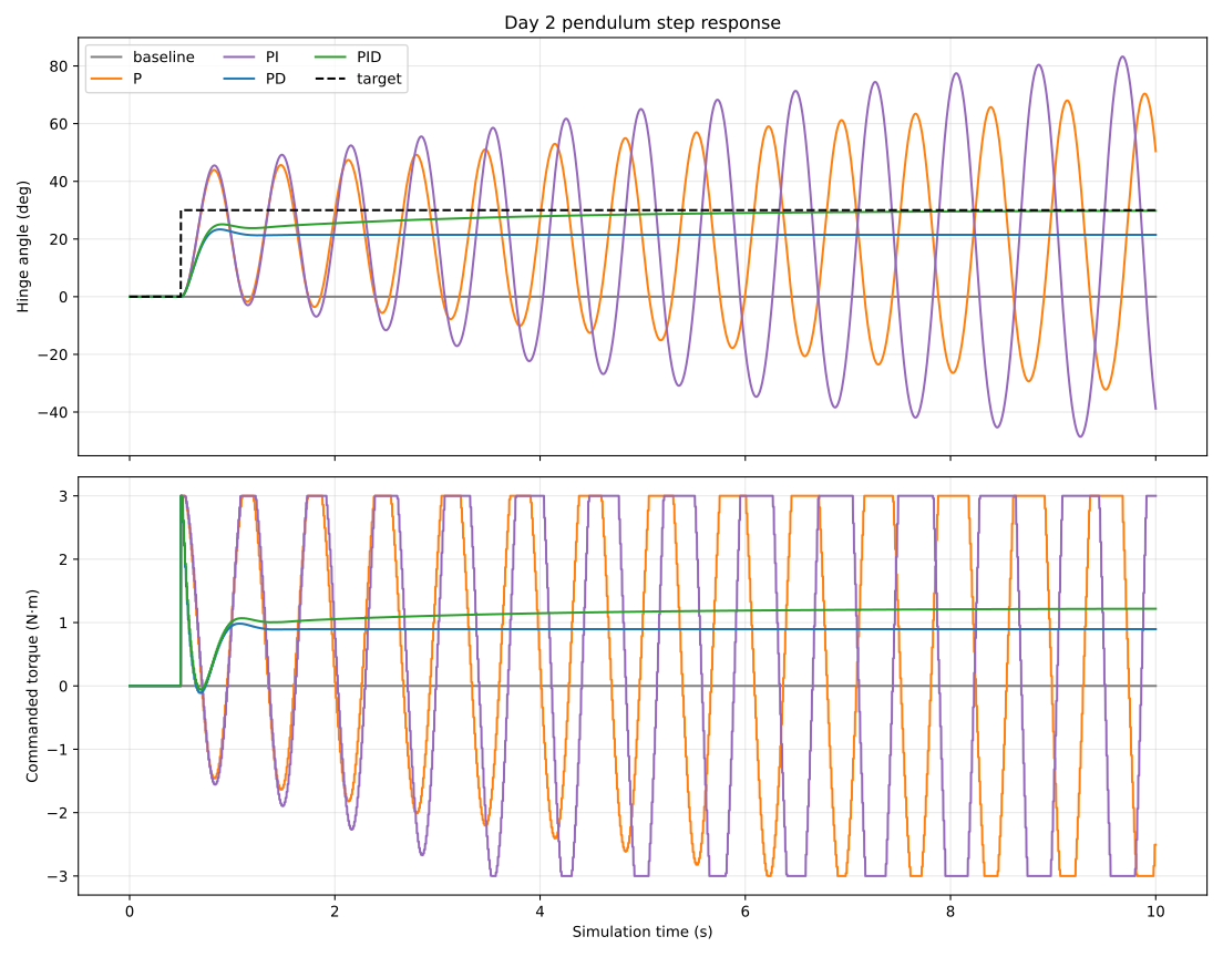
Figure: angle and commanded torque for all five conditions, plotted from the verified trajectories.csv (25,005 rows). The dashed line is the +30° target after 0.5 s. This is a data plot, not a photo of a physical robot — no physical robot exists yet. The original PNG is in the repository at experiments/day02/comparison.png.
8. Reading the results
The baseline's 0° overshoot is not successful control. It stayed at 0° because it began at the downward equilibrium without torque. It never approached the +30° target and retained a 30° error. Zero overshoot here means nothing moved, not that something was controlled well.
P and PI oscillated and never settled. P saturated on 36.9% of controller updates and PI on 49.8%; both swung past the target repeatedly (40.396° and 53.249° overshoot). PI's final-window error (41.815°) was worse than P's (33.191°) — integral action alone did not improve the observed error in this 10 s window, and the extra integral accumulation fed the oscillation. This contradicted the simple expectation that PI would reduce error.
PD damped the motion but kept a gravity offset. No overshoot, saturation on only 0.1% of updates, RMS torque the lowest of the four controllers (0.881 N·m) — but a final-window MAE of 8.560°. Without an integral term, PD has no mechanism to learn the 1.22625 N·m holding torque: at the target, the proportional term is zero, so the pendulum settles where gravity torque and proportional torque balance — below the target.
Only PID met the settling rule. It combined derivative damping with integral correction: settled 3.630 s after the step, final-window MAE 0.313°, no overshoot, RMS torque 1.124 N·m, saturation 0.1%. It was best on these metrics, with these gains, on this model. That does not establish that PID is generally best.
9. What the torque traces show
The bottom panel of the figure is as informative as the top. P and PI spend most of the run pinned at ±3 N·m — the actuator is saturated, so the controller has no authority left to shape the response; it is banging between limits while the pendulum swings. PD and PID almost never saturate, and their torque traces converge toward the holding torque: PD settles near 0.88 N·m (below the 1.22625 N·m needed, consistent with its angle offset) while PID settles near 1.22 N·m, matching the computed holding torque. Effort and accuracy agree: PID used more torque than PD (RMS 1.124 vs 0.881 N·m) and bought the remaining 8° of accuracy with it.
10. Failures, limitations, and lessons learned
- Idealised model. The Day 1 rod and hinge plus a direct torque motor. The effective inertia and gravity holding torque are simulator-derived, not hardware measurements. There is no sensor noise, no delay beyond the 0.01 s update interval, no friction beyond joint damping, no motor electrical dynamics, no mechanical backlash, and no contact.
- One of everything. One initial state, one target step, one gain set, one torque limit. A longer run or different gains could change the comparison — the P/PI responses remained finite and under one revolution but never settled, and a longer window might let PI converge or might not. That is untested.
- No physical-correctness claim follows from deterministic tests. The 16 tests check the controller, the adapter, the metrics, and the experiment runner — they do not check the model against a real pendulum. A second run on the same machine produced identical numerical summary values, identical 25,005 CSV rows, and an identical plot; only the summary recording timestamp changed. Repeatability on one machine is the baseline, not proof of physical accuracy.
- Lesson for the project: choose gains from the model before comparing, write down the hypothesis before running, and report the metric that contradicts the hypothesis (PI worse than P) instead of hiding it. The comparison is only trustworthy if the losing controllers are shown in full.
11. Reproducibility
From the repository root, with Python 3.11 and uv installed:
uv sync --locked --python 3.11
uv run --locked --python 3.11 pytest -q
uv run --locked --python 3.11 python -m mochi_sprout.experiments.day02 --output-dir experiments/day02
The timestamp changes on rerun. Numerical trajectories were reproducible on the development machine; different platforms may differ slightly. uv lock --check --python 3.11 passed.
Relevant files (merged main commit dc24cd5868e3caf548befe0f8e7c8b1415454437, PR #1, building on Day 1 commit b387c803a7ddf6192ace782515fff94377a7ff95):
- src/mochi_sprout/control/pid.py
- src/mochi_sprout/simulation/controlled_pendulum.py
- src/mochi_sprout/evaluation/control_metrics.py
- src/mochi_sprout/experiments/day02.py
- experiments/day02/README.md
- experiments/day02/summary.json
- experiments/day02/trajectories.csv
- experiments/day02/comparison.png
- docs/phase0-day2.md
- docs/publication/day02-evidence.md
- tests/test_pid.py, test_controlled_pendulum.py, test_control_metrics.py, test_day02_experiment.py

12. Modular open-source architecture
Day 2 keeps the Day 1 structure and adds one layer of separation. Generic code lives in src/mochi_sprout/control/ (the PID class, no MuJoCo import). Robot-specific simulation lives in src/mochi_sprout/simulation/ (the adapter that sets data.ctrl[0]). Evaluation lives in src/mochi_sprout/evaluation/ (it reads trajectories, never changes the simulation). Experiments live in src/mochi_sprout/experiments/ plus one folder per dated experiment under experiments/ with its own README, JSON, CSV, and plot.
Another controller can implement the small reset / update / saturated interface and be compared on the same model without modifying the physical model. That is the interface the next milestones will use — including, eventually, a learned controller on the same pendulum.
The repository is Apache-2.0. Character artwork, logos, and branding may require separate licensing; this release includes no such assets.
13. Next engineering question
Day 2 answers one question — can a classical controller hold this pendulum at +30° — and opens the next: how robust is that answer? The PID result holds for one gain set, one target step, no delay beyond the 0.01 s update interval, and no model uncertainty. Varying the gains, adding sensor delay, and perturbing the model parameters would show whether 3.630 s and 0.313° are a property of the controller or an accident of the setup. That robustness work is outside this Day 2 scope; it is the next experiment, not a claim in this article.
Day 1: Building Mochi Sprout: My First Physics Simulation with MuJoCo
Updated 11/6/2026